PROGRAMMING MANUAL LEDO-PM-001 / Rev 0.1 / 15 Oct 2026
DRAFT - NOT FOR RELEASE. Based on the existing programming, instruction and quick-start documents. Register information is transcribed, not firmware-verified. Examples are illustrative and have not been tested on hardware.
LED_O
Programming Manual
Browser configuration and Modbus TCP integration for controls engineers, PLC programmers and commissioning personnel.
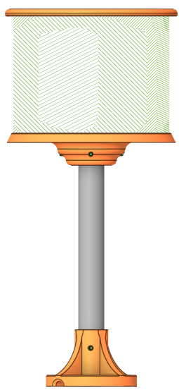
Illustrative product rendering
1. Network and browser access
Factory IP / subnet mask
10.0.0.49 / 255.255.255.0
Factory gateway / DNS
10.0.0.1 / 10.0.0.1
Browser / Modbus endpoint
https://10.0.0.49 / TCP port 502
Install and power the unit using the Quick Start Guide and approved installation instructions. Connect to an isolated commissioning network.
Set the PC to an unused address on the same subnet, for example 10.0.0.100 with mask 255.255.255.0. Open the device address in a browser.
Verify device identity if a certificate warning appears; follow the approved certificate procedure. Use manufacturer-provided credentials where requested.
Configure one factory-default device at a time. Assign a unique operational IP; record the device reference, address, firmware version, date and responsible engineer.
Reconnect at the assigned address and verify access. Change default credentials where supported before routine operation.
The original quick-start specification also lists 192.168.1.50. The address above agrees with both other manuals and its separate Ethernet table; check the release firmware. Do not assume network changes are persistent until a controlled restart confirms them.
Network security: keep Modbus TCP on a controlled automation network; do not expose the device directly to the internet. Confirm authentication, certificate management and access restrictions with the manufacturer. A browser HTTPS interface does not imply that Modbus TCP traffic is encrypted.
MES LED_O
MODBUS TCP INTERFACE DRAFT - NOT FOR RELEASE
2. Modbus TCP interface
The PLC or commissioning application acts as the Modbus TCP client; LED_O supplies the server interface. Use the assigned device IP and port 502. The source quick guide specifies one TCP client; confirm whether this limit applies only to Modbus connections.
Supported functions
Function
Operation
Use in the source map
FC03 / 0x03
Read holding registers
Readback; RFVAR is explicitly read-only
FC06 / 0x06
Write single register
Font, unit, decimals, scale, alarm and text-gap settings
FC16 / 0x10
Write multiple registers
Geometry, grouped display settings, text and variable data
Addressing and data conventions
Tables reproduce the source addresses starting at 0. Confirm whether those numbers are wire offsets before issuing requests.
Client tools may display one-based holding-register references. If address 0 is confirmed as wire offset 0, it may appear as 40001 in a client using that convention. Do not send 40001 as an offset.
A Modbus register is 16 bits. Modbus defines high-byte-first encoding within a register; application-level string packing and multi-register word order still require confirmation.
The unit identifier, readable ranges, exception responses, timeouts and persistence rules are not specified by the source documents. Do not assume defaults.
Documented FC16 write groups
Start
Count
Values in register order
0
4
POSX, POSY, ENDX, ENDY
4
4
SHAPE, SHAPE_Q, SHAPE_WEIGHT, SHAPE_COLOR
8
2
BITMAP, BITMAP_Q
10
2
BORDER_WEIGHT, BORDER_COLOR
12
3
TEXT_POSX, TEXT_POSY, TEXT_COLOR
24
2
ROTDIR, ROTSPEED
26
2
FILL_SCREEN, FILL_COLOR
Use documented groups rather than arbitrary writes across unrelated registers. A grouped request does not by itself prove an atomic display update; confirm update triggers and rendering behaviour. No register 29 definition is provided.
First read: after confirming addressing and the unit identifier, request one holding register at address 28 (TEXT_GAP) with FC03. Log the value and response. No default value is assumed; this is a proposed commissioning check, not a hardware-tested example.
The source states a typical response below 10 ms without test conditions. Do not use that figure as a guaranteed timeout or polling interval. Establish conservative, validated request timing for the installed firmware and network.
MES LED_O
CONTROL REGISTER REFERENCE DRAFT - NOT FOR RELEASE
3. Control register reference
Write functions are transcribed from the quick guide. FC16 entries form the groups on page 2. Coordinate origin, axes, endpoint inclusion, supported ranges and readback permissions require firmware verification.
Data types: int16 and uint16 are the source map's signed and unsigned 16-bit labels. Their representable ranges are -32768 to 32767 and 0 to 65535 respectively; these are not guarantees that every value is valid for a particular setting.
Unsupported addresses, values and function combinations must not be used until behaviour is defined. Do not assume every writable register is readable or that settings survive power loss.
MES LED_O
TEXT / NUMBERS / COLOUR DRAFT - NOT FOR RELEASE
4. Text, numbers and colour encoding
String and variable registers
Start
Name
FC / maximum
Source description
30
TEXT
16 / 30 registers
60-byte storage; null-terminated custom message packed into registers
60
IVAR
16 / 10 registers
Integer variable display with selected SI suffix
80
WFVAR
16 / 2 registers
Write floating-point value, 4 bytes per register pair
90
RFVAR
03 / 2 registers
Read floating-point value; read-only
Text packing
Choose a font with FONT_TYPE, write position and colour using the group at 12, then send the message to TEXT using the validated packing convention. The source does not define character encoding, high/low character order, padding, the required write length or whether the null terminator is included in the stated capacity.
Illustration only: ASCII, high-byte-first characters, null padded
"READY" + NUL: 52 45 41 44 59 00
Candidate register words: 0x5245, 0x4144, 0x5900
Do not transmit until the firmware packing convention is confirmed.
The illustration shows a possible encoding, not a verified device command. Shorter messages may leave stale content unless firmware clears or terminates the previous text correctly; include this in testing.
Numeric values
SI_UNIT selects a suffix and SI_DECIMAL selects 0-3 decimal places. Confirm the suffix enumeration, integer payload layout, decimal scaling and how numeric writes interact with TEXT. A two-register float occupies 32 bits, but the source does not establish IEEE 754 representation or register word order.
Do not infer that RFVAR echoes WFVAR or that alarms use the same data path. Verify the readback meaning, value source, rounding, negative values and invalid/overflow handling.
Colour input versus displayed output
The register map specifies RGB565 uint16 colour input. The confirmed display output is 14-bit, with limited light-shade reproduction due to the BAM implementation. A 16-bit register does not imply 16-bit displayed colour depth.
Standard RGB565 encoding reference
Input
Hex word
Decimal word
Red component maximum
0xF800
63488
Green component maximum
0x07E0
2016
Blue component maximum
0x001F
31
All components maximum
0xFFFF
65535
These are standard input encodings, not measured output shades or brightness guarantees. Confirm the firmware mapping; do not mask or shift values to 14 bits solely because the displayed output is 14-bit.
MES LED_O
DISPLAY CONTROL WORKFLOWS DRAFT - NOT FOR RELEASE
5. Display-control workflows
First establish a visible baseline through the browser's Control page, as described in the Instruction Manual. Use the corresponding register groups for PLC integration. Exact browser labels, save/apply actions, command priority and persistence must be checked on the release firmware.
Function-to-register guide
Function
Configuration path
Check on the device
Geometry
FC16 start 0, count 4
Coordinate origin, axes, clipping and endpoint inclusion
Shapes
Geometry, then FC16 start 4, count 4
Shape, quantity, line weight, colour and update trigger
Bitmaps
Geometry, then FC16 start 8, count 2
Image index, quantity, layout and rotation clarity
Border
FC16 start 10, count 2
Weight and colour; weight 0 means no border
Text
FC06 at 15; FC16 at 12 and 30
Font, position, colour, encoding and termination
Scrolling
FC16 start 24, count 2; FC06 at 28
Direction mapping, speed units, static mode and repeat gap
Background fill
FC16 start 26, count 2
Enable value, fill colour and interaction with other layers
Process value / alarms
FC06 at 16-23; appropriate data write
Units, decimals, scale and threshold colour behaviour
Shapes and bitmaps
The Instruction Manual describes rectangle, circle and triangle controls. The register map additionally lists SLINE and LINE; verify support and interpretation before use. Confirm how shape quantity affects spacing and whether changing a group immediately redraws the display.
The source describes ten built-in bitmaps, indexed 0-9, limited to 32 × 32 pixels, with up to four displayed across the screen. Confirm these limits and image-index assignments on the installed firmware. A full-size bitmap can occupy the space needed for a visible border. User-image upload format, size limits, storage and replacement behaviour remain undocumented.
Worked bench-test sequence: short status message
Use the browser to show READY and establish a known visible baseline. Suspend competing PLC writes while testing.
Choose a supported font, for example FONT_TYPE 0 (Arial8x11), using FC06 at address 15.
Choose a validated text origin and RGB565 colour. Write TEXT_POSX, TEXT_POSY and TEXT_COLOR together using FC16 at 12, count 3.
After validating encoding, pack the message and terminator for TEXT at 30. Confirm the permitted write length before transmitting.
Check the physical display, then test a shorter message and reconnect. Record whether configuration survives a controlled restart.
Alarm validation: test values below, at and above both thresholds. Determine equality behaviour, hysteresis, alarm priority, recovery colour and behaviour on stale/lost input. The source does not define these rules; do not use the display as a safety-related alarm function.
MES LED_O
PLC INTEGRATION / SUPPORT DRAFT - NOT FOR RELEASE
6. PLC integration and troubleshooting
Use the PLC vendor's supported Modbus TCP client block or a maintained Modbus library. The sequence below is platform-neutral design guidance, not executable code or a tested PLC program. No vendor-specific memory addresses are required by LED_O.
CONNECT to assigned LED_O IP, TCP port 502
READ confirmed address 28, count 1, using FC03
IF response is valid:
    SEND only approved configuration groups, one request at a time
    WAIT for each response before issuing the next request
    UPDATE process data at a validated application interval
ELSE:
    RECORD the fault and apply bounded reconnect/retry handling
    FLAG communication loss to the machine control system
ON reconnect:
    RECHECK device state before resuming writes
Do not assume retained settings, automatic blanking, a communications watchdog or any defined display state on disconnection. Establish and test the required fault response in the overall control system. Do not repeatedly overwrite settings from every PLC scan without a validated reason.
Diagnostic checks
Symptom
Checks
Browser unavailable
Power, Ethernet link, PC subnet, assigned IP, duplicate addresses, HTTPS and certificate handling
Browser works; Modbus fails
Port 502, client limit, firewall rules, unit identifier and device addressing
Modbus exception
Record the exception; verify function, address, group length and value range against approved firmware documentation
Text corrupt or incomplete
Character encoding, byte packing, terminator, write length and previous-message clearing
Wrong numeric value
Signedness, payload layout, decimal scaling, float representation and word order
Confirm firmware/version coverage; addressing and unit identifier; readable/writable ranges; supported groups and value limits; string/number packing; SI suffix and direction enumerations; bitmap catalogue/upload; mode priority; alarm behaviour; persistence; connection limits; timeout and reconnect behaviour. Capture approved UI screenshots and test every worked example on a named PLC/software version.
Contact mes@led-o.ddns.net with the device reference, firmware version, PLC/software version, network settings, function/address/count, transmitted values and observed response. Do not send passwords or other credentials.
Source basis: existing Programming Manual outline, Quick Start Guide register tables and Instruction Manual display-control descriptions. Compliance declarations are separate controlled documents; the unfinished declaration section in the source Word file is not reproduced as a conformity claim.