DRAFT - NOT FOR RELEASE. Converted from the existing Quick Start Guide and checked against the instruction and programming manuals. Unresolved installation and protocol details require engineering approval.
LED_O
Quick Start Guide
Install the device, establish browser access and check Modbus TCP communication before integrating it with a machine.
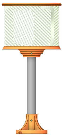
Illustrative product rendering
1. Before you begin
Check the device, power cable, Ethernet cable and ordered mounting accessories for damage.
Prepare a 24 V DC supply, a commissioning PC with Ethernet and a compatible web browser.
For PLC control, use a Modbus TCP client supporting the required FC03, FC06 and FC16 functions.
Use a separate indication method wherever loss of this display could create a hazard; do not rely on the display as a safety function.
2. Mount and connect with power isolated
Secure the supplied mounting arrangement in a position visible to the operator. Obtain the approved mounting drawing for hole positions, fixings and clearances.
Support the cables against pulling, crushing and repeated flexing. Keep power and communication wiring away from high-current and switching circuits.
Connect Ethernet to an isolated commissioning network or PC. Keep the power supply isolated while connecting the supply wiring and functional earth for EMC.
Connection overview, not a connector pinout. For browser commissioning, use a PC instead of the PLC. Green conductor: functional earth (FE) for EMC return paths; not drawn above.
Functional earth for EMC: LED_O is a low-voltage device powered by 24 V DC. The green conductor provides an EMC return path, not a protective-earth safety connection. Install this functional-earth connection in accordance with the manufacturer's EMC installation requirements.
IP65: dust-tight and protected against water jets; not suitable for immersion. Follow the approved installation instructions to maintain enclosure protection. Never connect directly to mains voltage or open the enclosure for commissioning.
MES LED_O
FIRST CONNECTION DRAFT - NOT FOR RELEASE
3. Establish network access
Factory IP address
10.0.0.49
Subnet mask
255.255.255.0
Gateway / DNS
10.0.0.1 / 10.0.0.1
Example commissioning PC
10.0.0.100 / 255.255.255.0, only if unused on this network
After approved installation checks, apply 24 V DC. With no Ethernet connection, the display may indicate that no network connection is detected.
Set the PC to a unique address on the same subnet. Connect one factory-default device at a time to avoid duplicate IP addresses.
Open https://10.0.0.49. If a certificate warning appears, verify the device identity and use the manufacturer's approved certificate procedure; do not disable browser security globally.
Use manufacturer-provided credentials if prompted. Assign a suitable unique operational IP address and record it. Reconnect at the new address and change default credentials where supported.
The original quick guide also lists 192.168.1.50. This version uses 10.0.0.49, consistent with its Ethernet table and both other manuals. Confirm against the release firmware. Do not expose the device directly to the internet.
4. Check the display and Modbus connection
Use the web interface's text-display controls to enter a short message such as READY. Select a visible text colour and confirm that the physical display changes. Exact control labels and apply/save behaviour require a firmware check.
Read-only Modbus check: connect to the assigned device IP on TCP port 502. Using FC03, read one holding register at the documented address 28 (TEXT_GAP). Record the returned value; no particular default value is assumed.
Confirm whether the client expects a zero-based offset or a one-based register reference, and confirm the unit identifier with the manufacturer. This example is derived from the source register map, not hardware-tested. Do not trial writes on an operational machine.
FC16 grouped writes from the source guide
Start
Quantity
Registers, in order
0
4
POSX, POSY, ENDX, ENDY
4
4
SHAPE, SHAPE_Q, SHAPE_WEIGHT, SHAPE_COLOR
8
2
BITMAP, BITMAP_Q
10
2
BORDER_WEIGHT, BORDER_COLOR
12
3
TEXT_POSX, TEXT_POSY, TEXT_COLOR
24
2
ROTDIR, ROTSPEED
26
2
FILL_SCREEN, FILL_COLOR
If connection fails: check power, Ethernet, the assigned IP, subnet and duplicate addresses. For Modbus, also check port 502, client addressing and other connected clients; the source guide specifies a maximum of one TCP client. If the browser works but the display does not change, consult the Programming Manual before changing registers.
MES LED_O
REGISTER REFERENCE DRAFT - NOT FOR RELEASE
5. Control registers
Addresses and write functions are transcribed from the original quick guide. FC06 writes a single register; FC16 writes multiple registers using the groups on page 2. Confirm address convention, valid ranges and firmware behaviour before writing.
Colour format is not display colour depth. The source register map specifies RGB565 values carried in 16-bit registers. The device's confirmed display output is 14-bit. Keep the documented register encoding when programming; limited light-shade reproduction results from the BAM implementation.
The original specification labels the output "16-bit (5-4-5)". That label has been corrected to 14-bit output. Firmware validation is still required to confirm precisely how each RGB565 input maps to the available display shades.
MES LED_O
DATA / SPECIFICATIONS / SUPPORT DRAFT - NOT FOR RELEASE
6. String and data registers
Address
Name
FC / maximum
Description
30
TEXT
16 / 30 registers
60 bytes; null-terminated custom message packed into registers
60
IVAR
16 / 10 registers
Integer variable display; appends selected SI unit suffix
80
WFVAR
16 / 2 registers
Write floating-point value, 4 bytes per register pair
90
RFVAR
03 / 2 registers
Read floating-point value; read-only
Confirm string character encoding, byte order, null-terminator capacity, integer packing and floating-point representation/word order before implementation. These details are not defined by the source quick guide.
7. Technical reference
Display
RGB; 32 × 124 pixels
Colour output
14-bit
LED / pitch
SMD2121 / 3 mm
Brightness
800-1200 cd/m², after diffuser
Viewing angle
≥140°; housing/diffuser limited
Panel native angle
≥160°, source value
Refresh / scan
≥1920 Hz / 1/16 scan
Dimensions
100 × 428.5 × 100 mm (W × H × D); confirm assembly
Weight
1.25 kg; confirm included hardware
Enclosure
ABS + polycarbonate diffuser
Protection
IP65; no immersion
LED lifetime
>50,000 h (L70), source value
Viewing height
Position for a clear line of sight
Supply
24 V DC ±10%
Current
Confirm: quick guide 1.1 A; instruction manual 1.25 A maximum
Protection
Reverse-polarity, over-current, over-voltage
Interface
Ethernet / Modbus TCP; PC browser (HTTPS)
TCP clients
1, source value; confirm scope
Response
<10 ms typical, source value
Operating
0°C to 60°C
Storage
-40°C to 85°C, source value
Humidity
30-90% RH, non-condensing
Firmware
v1.0.0-R in source; verify installed version
Update method
Ethernet, internal service tool
Unverified mechanical test claims from the source: vibration 10-50 Hz, 10 m/s² for 10 min; damage-limit vibration 10-50 Hz, 20 m/s² for 2 h; drop 1 m onto concrete. Confirm reports and conditions before release. The source's inconsistent "1 m (5 ft)" conversion is not retained.
The original Word guide retains the dimension illustrations. Obtain an approved dimensioned drawing before drilling or fabrication. Support: mes@led-o.ddns.net.
Release checklist: confirm current ratings; align the Instruction Manual with the functional-earth EMC connection; approve mounting and cable details; hardware-test browser and Modbus steps; complete protocol packing details. EMC testing is reported passed by the manufacturer; formal laboratory documentation is pending. CE/UKCA marking is not claimed complete in this draft.